A transformative solution for architecture, engineering, construction, operation & maintenance.
What is BIM?
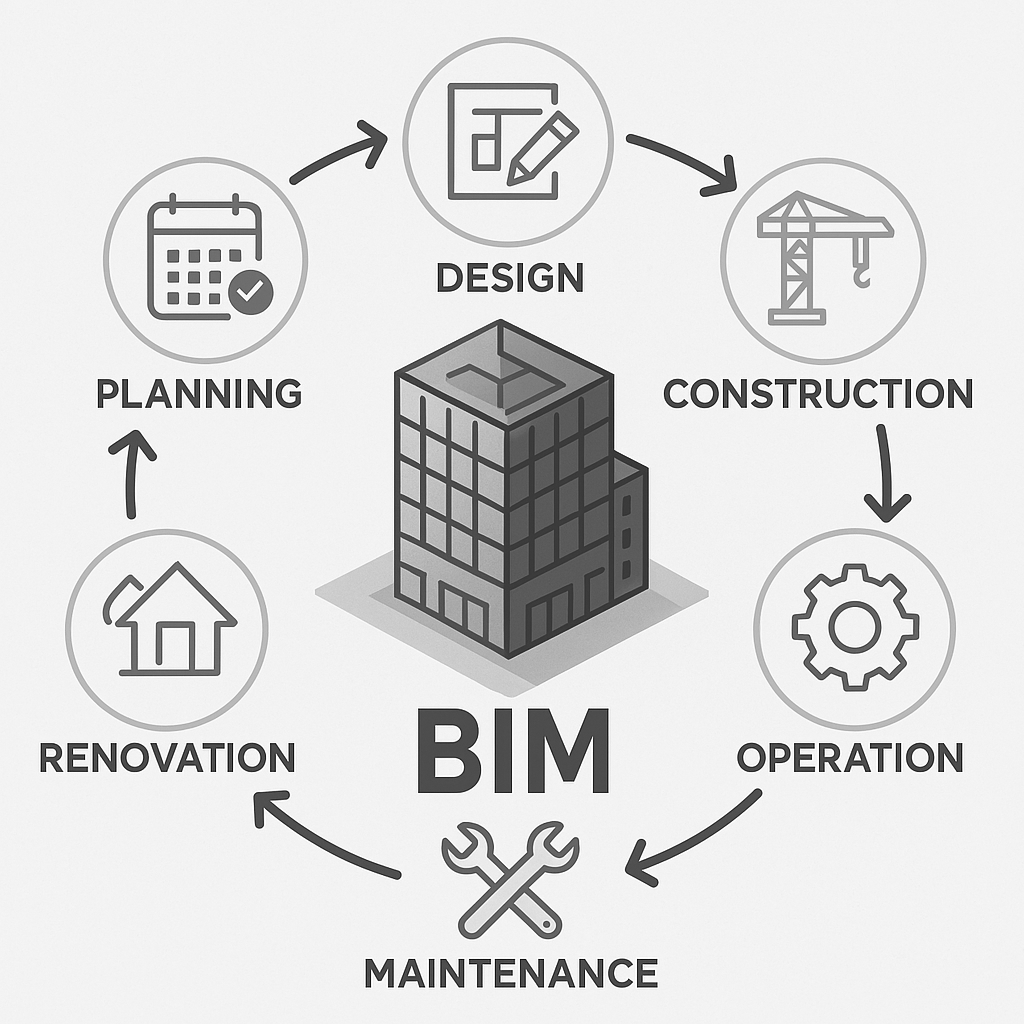
BIM (Building Information Modeling) is a process of creating, managing, using digital representation of physical buildings. It enables AECOM (architecture, engineering, construction, operation & maintenance) professionals.
BIM lets you plan, design, construct, manage, operate, and maintain buildings throughout its life-cycle more efficiently.
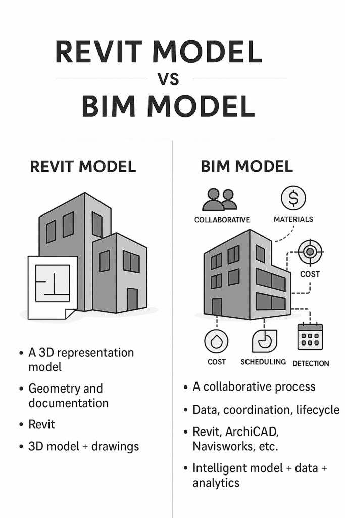
BIM creates a complete digital representation of a building, not just 2D drawings or 3D Models.
- BIM is a Process
- BIM is a Geometric Model
- BIM is an Information System
- BIM is a Data Source
- BIM is a Management Tool
- BIM is a Visualization Platform
- BIM is a Collaborative Environment
BIM is a Process, What does this mean?
It’s a simple step-by-step process. In the planned workflow, create, manage, and share the BIM data package throughout the project lifecycle. On a single common data environment, collaborate on the project from start to finish.
What is BIM as geometry?
Geometry in BIM is refers to the 2d, 3d shape & spatial definition of all building elements. This geometry is based on the Level of Definition of each element.
What is Information in BIM?
The term “Information” in BIM is the structured way of assigning meaningful values to building elements.
| Building Element | Information Attached |
| Wall | Type = Partition Wall, Material = Brick, Fire Rating = 2hr |
What is Management in BIM?
Management in BIM means planning, organizing, monitoring, and maintaining the digital transformation. Ensure right data is created, shared, and updated for making BIM projects, using BEP (BIM execution Plan).
Alongside, set up standards & protocols, coordinate with teams, manage clashes & monitor project delivery.
What is Visualization in BIM?
Visualize digital models made by BIM in real-time. Present, understand and analyze the design, construction sequence, and operation of the building. This powers the popular term ‘Seeing is believing’.
Visualization in BIM helps you to understand the design intent, coordinate between disciplines, energy analysis simulation, and decision making in construction.
What is Collaboration in BIM?
It’s a way of coordinated workflow by multiple stakeholders such as architects, engineers, contractors, and owners. Each model is worked on a single common data environment. This solves issues prior to construction, leading to fewer errors, better decisions, increasing efficiency in the project.
Core of BIM: Explained in Detail
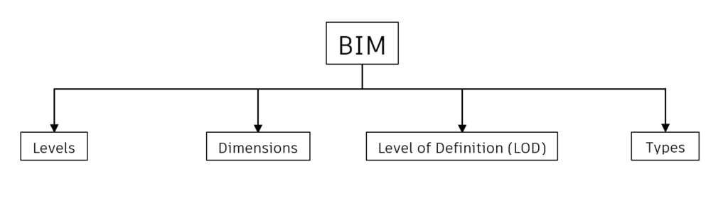
Levels
- Level 0
The project is made using 2D CAD design, drafting techniques in the form of drawings (plans, sections, elevations) with no collaboration via paperwork or email.
Use Cases
- An architectural firm designs a residential building using AutoCAD. They send PDF floor plans and elevations to the structural and MEP teams separately via email.
- No 3D model exists, and every collaboration or coordination is done manually.
2. Level 1
This level is the transition of using both 2D drawings & 3D cad models. This 3D cad models are just used for conceptual work. 2D Cad drawings are shared via Single Common Data Environment (CDE).
Use Cases
- The architect uses AutoCAD for 2D floor plans and SketchUp for 3D visuals.
- The structural and MEP engineers work on separate AutoCAD files using Xrefs.
- All 2D drawings are uploaded weekly to a shared drive (CDE).
- Coordination is still manual — errors are discovered during construction, not design.
3. Level 2
The project is built on a Full Collaboration Scale, where each team will produce their own Federated model with their discipline specific data, shared via CDE. This model is combined as One Unified Model.
Use Cases
- Architects model the building shell in Revit.
- Structural engineers creates Tekla model of beams, columns, and foundations.
- MEP engineers model ducts and pipes in Revit MEP.
- All models are exported as IFC and shared through a Common Data Environment.
- A BIM Coordinator uses Navisworks to link these models and run clash detection.
- Quantity Surveyors extract data for 5D estimation using the model.
4. Level 3
This is a Full Integration level, where the project model is kind off shared in which all the stakeholders, project teams will work on a single Model file, enabling Real-time collaboration within the same CDE.
Use Cases
- The architect, structure, and MEP teams all work on the same cloud-based Revit model using Autodesk Construction Cloud.
- The contractor uses the same live model to plan sequences and generate quantities.
- The facility manager accesses the same model to manage operations, maintenance schedules, and performance.
- All stakeholders can collaborate in real time, comment on the model, and track changes.
Dimensions
2D: CAD drawings made up of lines and splines, only in the X and Y axis.
3D: Model made with geometry in the X, Y, and Z axes.
4D: Scheduling time to sequence the data helps in construction planning and progress tracking.
5D: Adding cost information to the components helps in quantity takeoff and budget monitoring.
6D: Sustainability and simulation aim at analyzing energy consumption and thermal performance to improve building performance.
7D: Facility management includes asset data, warranty, and maintenance information, helping in building life cycle management.
8D: Embeds safety planning into the model, used to analyze hazards, identify risks, and support training.
9D: Reducing waste, maximizing efficiency, and optimizing the construction process — leading to Lean Construction.
10D: Full life cycle management and industrialization of buildings, through advanced digital integration.
Level of Definition (LOD)
The Level of Definition is classified into three. They are:
- Level of Detail
| LOD | Represents |
| 100 | Concept – a space or location of AC unit |
| 200 | Schematic – approx. shape, size, position |
| 300 | Design – Accurate geometry & dimensions |
| 350 | Construction – includes connection details, shop level model |
| 400 | Fabrication – Fabrication details will be added |
| 500 | As-built – Actually built data verified |
Focus more on visual geometry with graphically detailed elements.
Example: Diesel generator
At Low LOD, will only have the outer Enclosure box, whereas at high LOD the element will have exact shape, size, internal components, handle, bolts & nuts.
As you add more detail to a model element, its level of detail increases progressively.
- Level of Development
This is the accuracy of geometry & data which includes location, dimension of each element, cost, specifications, and material.
Example: Diesel Generator
Location of element: Basement Floor
Dimension: Length= 2m, Width= 1.5m, Height= 1.2m
- Level of Information(LOI)
These are data present to the elements in the form of metadata or parameters.
Example: A diesel generator
| Manufacturer | Kohler Power |
| Model | KD1100-E |
| Material | Forged steel |
| Fuel | Diesel |
| Warranty | 30 months from the date of purchase |
Note: Individual elements, objects present in the model contribute the LOD
Types
- Closed-BIM: This is a type of BIM workflow where all members in the project use the same software platform.
- Example: Autodesk Revit will be used by all stakeholders, project members.
- Files will be shared as native format only (.rvt).
- Open-BIM: This is a type of BIM workflow where any member can use any different software.
- Example: One project team (MEP team) may use Autodesk Revit, while another project team (Architect team), either internal team or external firm uses ArchiCAD or another software.
- Files will be shared as IFC.
- Imported into the respective software platform
Standards & Codes
| ISO 19650 | Information Management using Building Information Modelling (BIM) |
| ISO 55000 : 2014 | Asset & Facility Management |
| IS 15183 | Guidelines for Maintenance management of Buildings |
| NBC Vol-2 Part-12 | Asset & Facility Management |
| BIM-FM | Facility Management Consortium BIM Guide v2_1 |
| IFMA | International Facility Management Association |
| BS 8210 : 2012 | Guidelines to facilities maintenance management |
| CMMS | Computerized Maintenance Management System |
| Cobie | Construction Operations Building Information Exchange |
How important is BIM to Digital twin?
BIM is extremely important to a Digital Twin — in fact, it’s often the foundation on which a digital twin is built. Without BIM, a digital twin has no geometry, no structured metadata, and no spatial context.
How is BIM useful in Digital Twins?
| Geometry and Asset Context | BIM provides accurate 3D geometry and locations of systems, rooms, equipment, etc. |
| Structured Data | BIM models contain key metadata (e.g., type, manufacturer, capacity, maintenance info). |
| System Relationships | BIM links parts of the system (e.g., HVAC ducts, electrical panels) logically. |
| Lifecycle Connection | BIM starts during design and construction; digital twin takes over at handover. |
| FM Integration | Without BIM, it’s difficult to track assets and link them to live building performance data. |
Without BIM (The Base Layer for Digital twin), A digital twin would be:
- Just raw sensor data without spatial meaning
- Harder to visualize
- Disconnected from facility operations or maintenance records
What is Digital twin?
A digital twin is a virtual representation of a physical object or elements or building, system, or process that is continuously updated with real-time data from the real world.
In simple terms, Digital twin is an extension of BIM connecting real world data into virtual BIM world through IoT, insights and real-time actions.
Digital twin is a combination:
Digital twin = BIM + Facility Management + Visualization + Asset Management + Lifecycle Management
What is needed for Digital twins?
- An AIM (Asset Information Model) made using BIM Model
- Format may be Revit, IFC
- Includes Geometries, System, and Asset Metadata.
- Asset Information
- Iot & Sensor data
- Platform for Integration
- Analytics & Insights
- API & Connectivity to BMS
- Access & Security
What is AIM?
AIM stands for Asset Information Model, which is built from PIM is a structured repository to operate, maintain & manage the built asset after a construction is complete.
Once the building construction is done, the PIM is validated, cleaned, and transformed into an AIM.
AIM contains asset data, COBie (Construction Operations Building Information Exchange) , O&Ms, Serial number, and Warranties.
This AIM (Asset Information Model) is transformed into BIM-FM (BIM – Facility Management) model which can be used to integrate with digital twins.
What is PIM?
PIM stands for Project Information Model, which is developed during the design, and construction of any building includes everything that is needed to plan, construct, and document a project.
This PIM is validated and converted into an AIM, which is used for Operations and Facility Management.
Guidelines for Facility Management Digital twins:
- The BIM-FM Model should be derived from AIM model.
- When Multi-disciplinary linked models are made, make the model into a Single Federated BIM Model.
- Remove unnecessary data such as Blank parameters, unnecessary views & sheets, annotations, unused families.
- All assets should have unique identifiers.
- All assets should be placed with accurate dimensions.
- Assets that are not present within a room should be captured via nearest room boundary.
- All assets should have a minimum Level of Information within their properties.
- Serial number
- Manufacturer
- Model
- Description
- All assets should be properly linked with appropriate tech spec sheets, installation manuals, and operation manuals in pdf format.
- The asset data or information should be retrieved from a centralized single source of truth, the BIM model.
BIM is not just about 2d or 3D, it's data, information, visualization, geometry inside buildings.
Author:

Ajay J S
Assistant BIM Manager

The views and opinions expressed in this blog are those of the author and do not necessarily reflect the official policy, position, or views of nhance.ai or its affiliates. All content provided is for informational purposes only.